Motivation
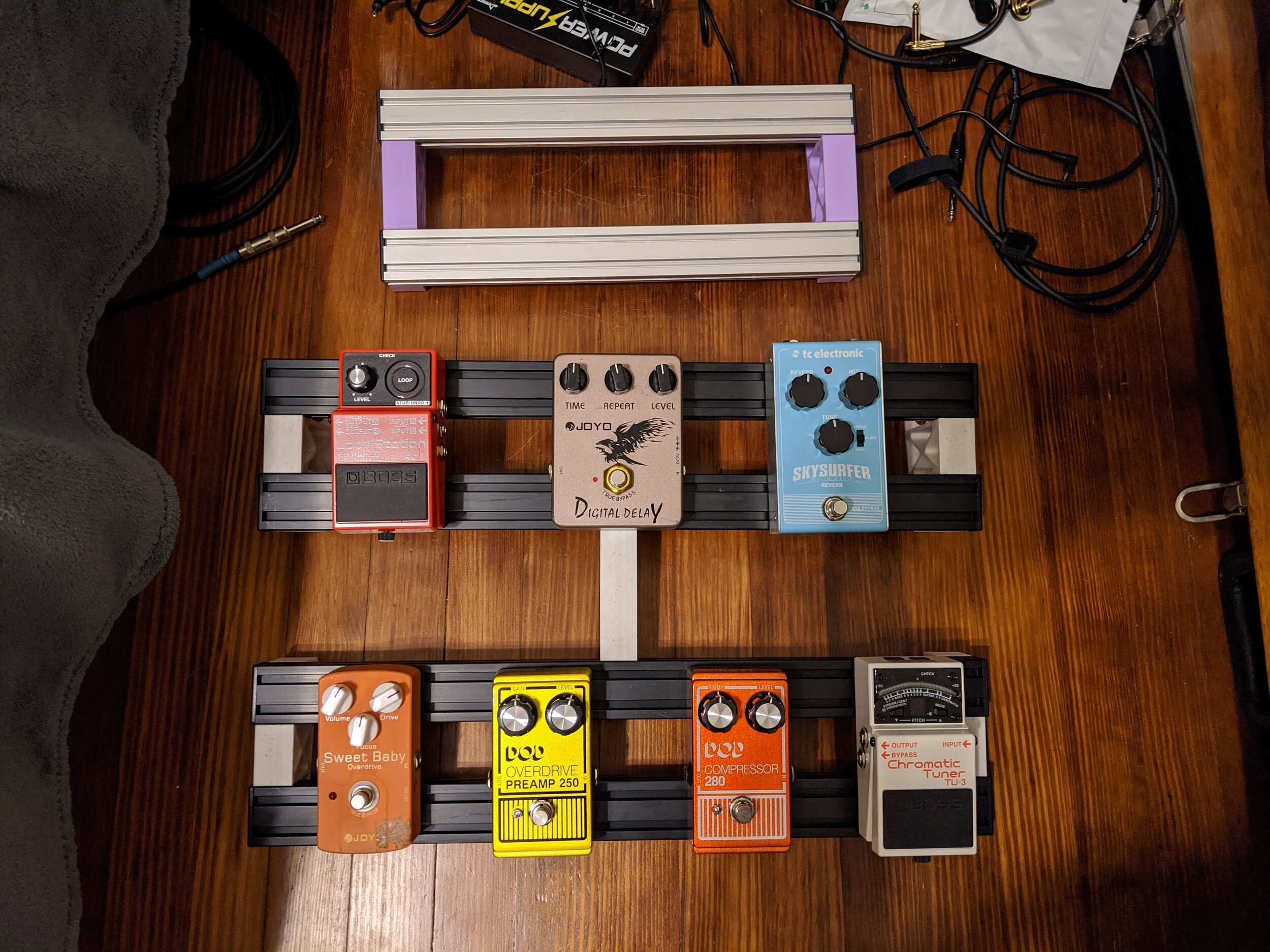
After building my new pedalboard (check out my build log here) and getting to play and practice with it, my fascination for effects pedals continued to grow. Looking at plenty of pedal breakdowns and builds, I was inspired and thought, “Maybe this is something I could do.” The first DIY pedal examples I looked at were a bit intimidating, though - while my background is in engineering, I’m more the nuts-and-bolts kind and taking on any pedal project would require lots of time and patience.
Through some research, though, I discovered that a foot switch would be a great start. My Boss RC-1 looper pedal has an input for one of their FS series switches to expand the pedal’s functionality. While it isn’t an effects pedal, per se, it’s useful, very cheap to build, and most importantly, very simple, and a great stepping stone to building DIY pedals.
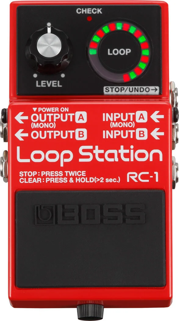
Picture of the Boss RC-1. Photo from the Boss website

The finished product
Process
FS-5 and FS-6 footswitch clones are very well documented across the internet. Access to lots of parts lists, diagrams, and step-by-step instructions gave me the confidence to move forward. For my build, I referred to this Instructable and all my parts were sourced from Love My Switches for about $10 US + shipping.
In my pedalboard build I took advantage of custom 3D printed bracketry, and I was curious how I could do something similar for the foot switch enclosure. This time, however, I wanted to do the entire enclosure. I incorporated a few things into the design based on other foot switches I had seen:
An angled face for the foot switches
The toggles mounted to the same face as the jack input to keep them out of the way
Embedded symbols to show the function of each switch
The geometry of the enclosure made for some really easy and quick prints. Once my parts were ready, I started assembly. This part was made straightforward as well, thanks to the clarity of the assembly instructions. At the end, I used M3 heat set inserts and M3 x 10mm SHCS to close it all up. Now I was ready to make some loops!
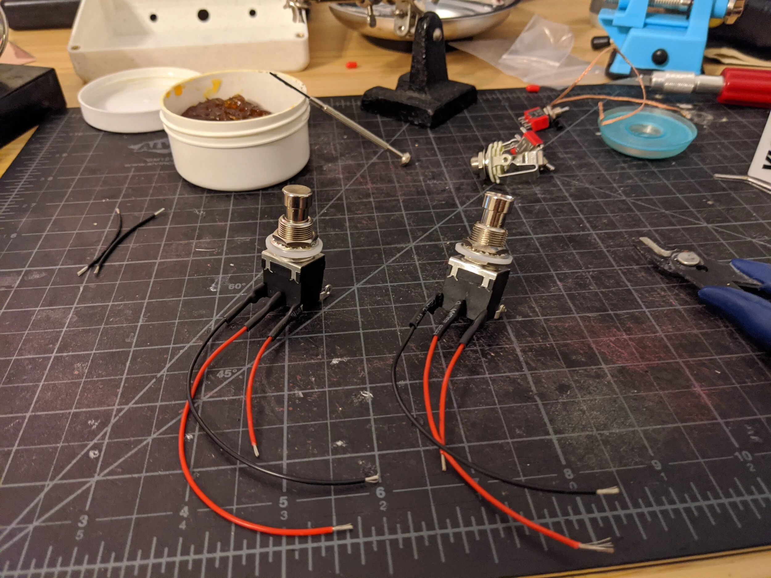
Wiring the momentary foot switches

Wired up with the toggles and input jacks (TRS)
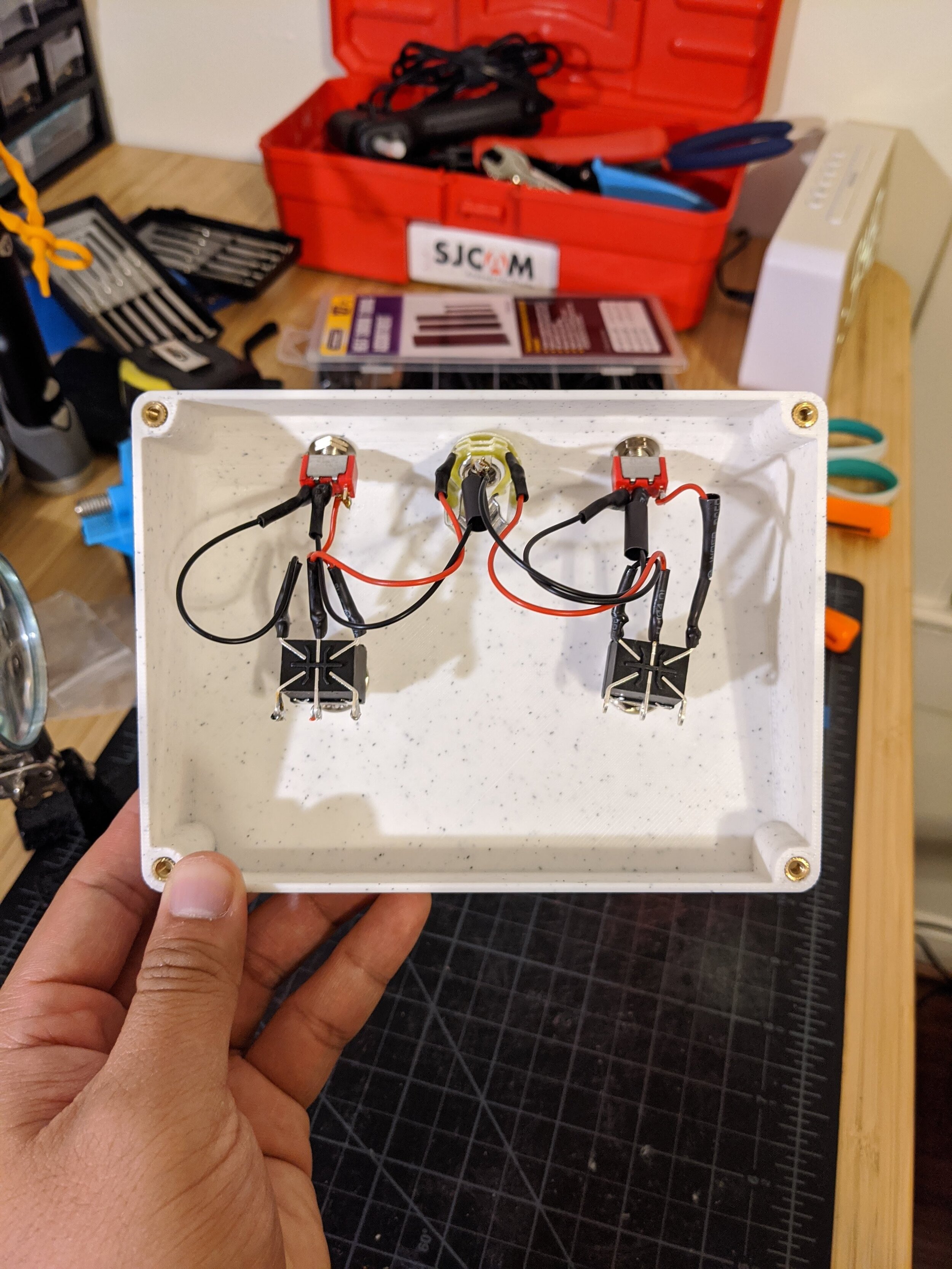
Internals of the enclosure with the components all installed

The base of the enclosure with built-in feet. There are counterbored through holes in the feet to neatly cover up the socket heads

The fully assembled foot switch. Check out the “undo/redo” and “stop” symbolism
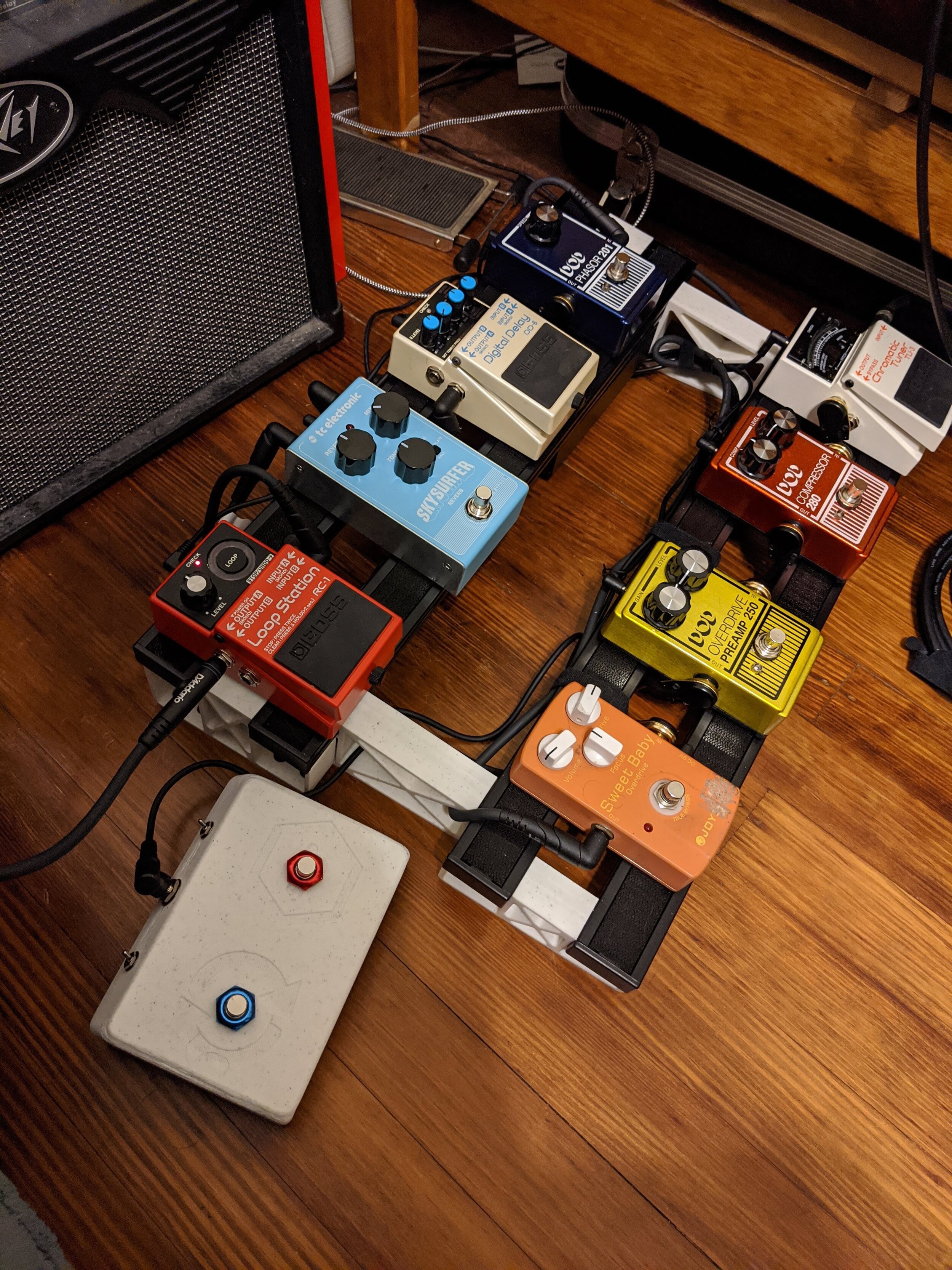
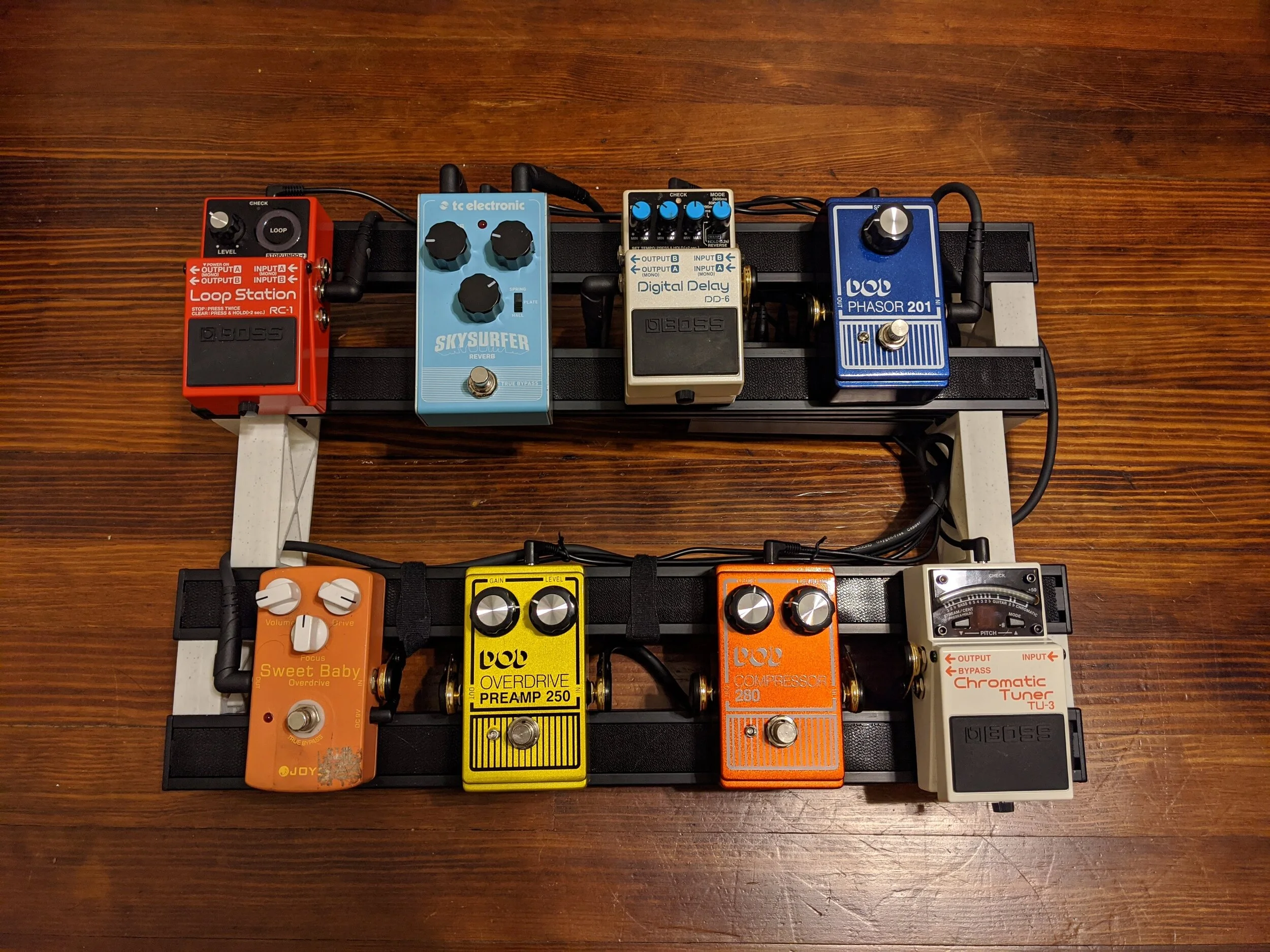
My FS-6 clone sitting pretty with the rest of the rig!
Conclusion
When I first plugged in my FS-6 clone and tried it out with the RC-1 I was a bit confused by the toggle configuration and how that affected the switch functions. The assembly instructions I used had no remarks on the toggle positions, so I just played around with them until they worked as intended. Once I got that down, though, the FS-6 clone worked like a charm! Here is the help page from Roland to get an idea of what the FS-6 can do with the RC-1.
In the end I think it makes the RC-1 looper a lot easier to use. There is less tap-dancing involved trying to hit the switch multiple times to get it to do different things. I will advocate for anything that gets you making music faster, instead of wasting time fiddling with settings.
The printed enclosure itself works fine - I say fine instead of great because it’s much lighter than its metal counterparts, which takes away from the experience a bit. It feels more like a toy than a piece of musical equipment. The other part of it is that the size is inconsistent with the standard enclosure sizes out there, so it doesn’t really have a spot on my pedalboard. As a side note, I did eventually purchase a small 1590A enclosure to try out with this circuit - I plan to switch these two out and see how it changes things.
All that being said, in the end, this thing is just really fun to play with and is a great addition to my RC-1. In addition, it was a very cheap, easy, and quick project to tip my toe into the pedal building world. I would definitely recommend this type of build for anyone looking to get started in DIY pedal hardware!